Performance target
Defined by the facility standard or project requirement—not by colour or appearance.
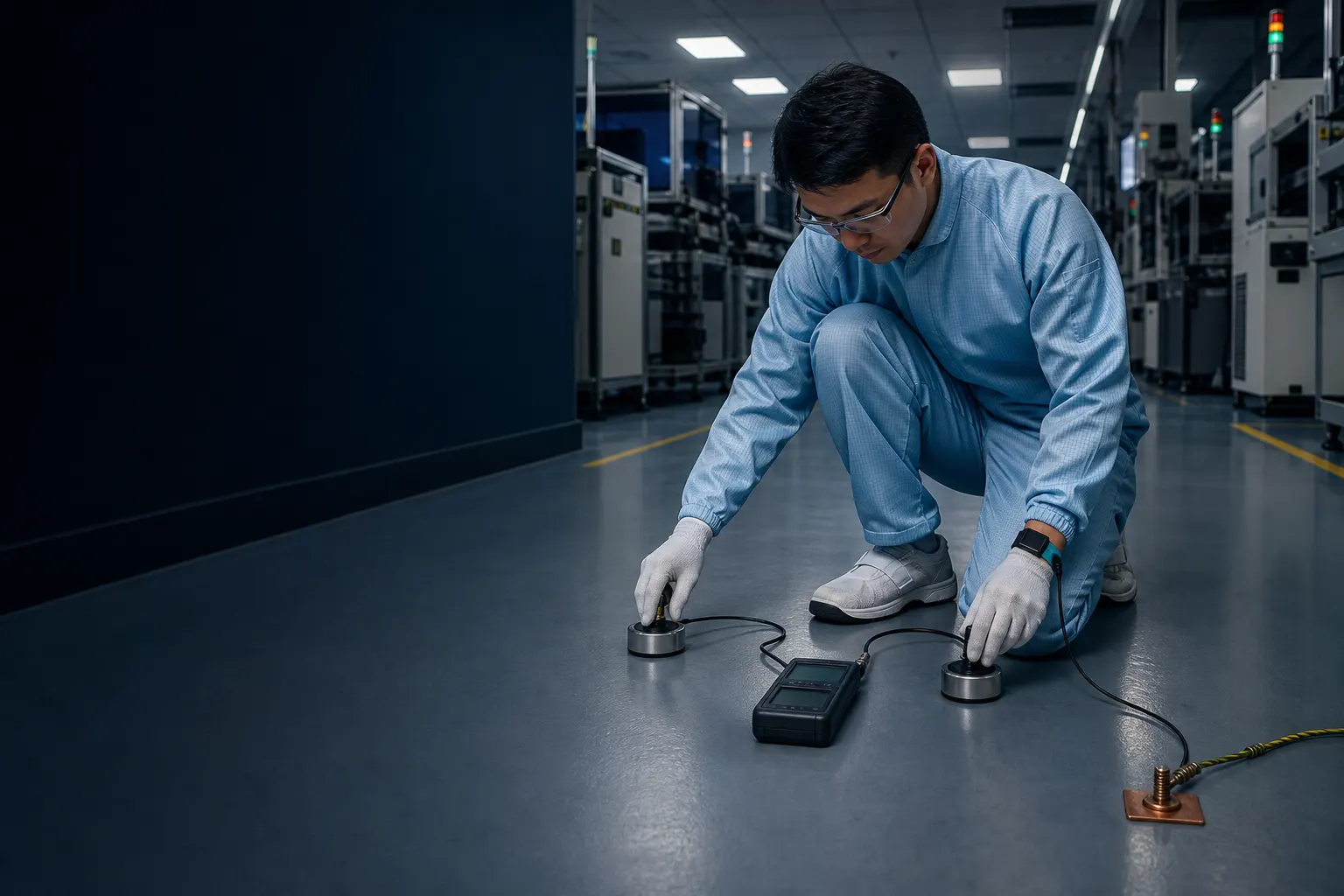
ESD CONTROL · CLEAN PRODUCTION · MEASURABLE PERFORMANCE
The floor is part of the ESD-control plan.
Electronics production floors must support the facility’s defined resistance, grounding, cleanliness and traffic requirements. Rayson helps project teams define the complete operating condition before selecting the coating system.
01 · Define before selecting
Start with the facility or project requirement: the applicable ESD target and test method, then the grounding layout, substrate condition, cleaning regime and traffic exposure. Only after these are known can the project team evaluate a complete compatible coating system and plan documented testing after installation.
Defined by the facility standard or project requirement—not by colour or appearance.
The coating, grounding points and building earth need coordination before work starts.
Cleanliness, traffic, cleaning and shutdown access all influence the system direction.
Agree who tests, how results are recorded and when the floor will be retested.
02 · One facility, different operating zones
Each zone places a different demand on static control, clean maintenance and mechanical wear. Select a zone to see what the project brief needs to establish.
Sensitive component handling
Define personnel movement, ESD footwear, workstation connections and the required test method. A clean-looking floor is not proof of electrostatic performance.

Cleanliness and uptime
Controlled areas also need particle control, seamless cleaning, equipment coordination, air handling and a realistic shutdown window.

Traffic and conductive continuity
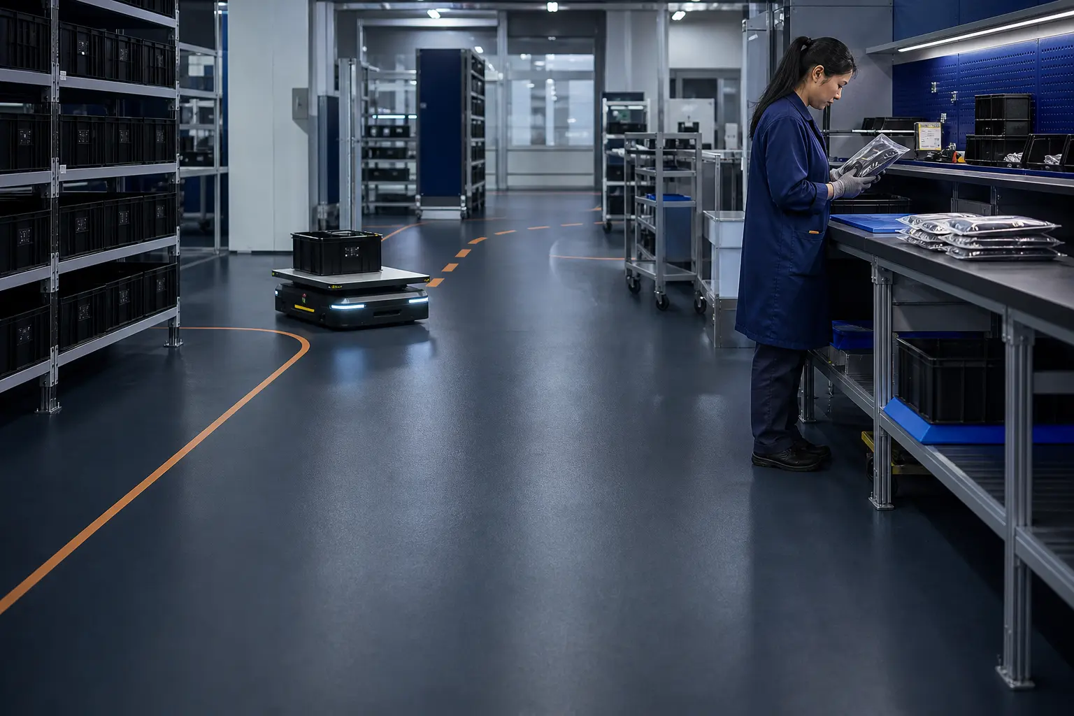
Trolleys, AGVs and packing operations create concentrated wear routes. The brief should address traffic, grounding and the maintenance plan together.
03 · One continuous, measurable path
This is an illustration of ESD system logic, not a universal specification. The final build-up depends on the project target, substrate and relevant product technical data sheets.
Assess strength, moisture, cracks and existing coatings.
Select compatible preparation and primer direction for the substrate.
Coordinate the conductive layer, grounding points and building earth.
Apply the confirmed system at its specified thickness.
Test after cure using the project method and record the result.
04 · Evidence before recommendation
Rayson’s technical direction starts with real project information and published product data. A single product should not be specified while the grounding, substrate or test requirement remains unknown.
Primary static-control finish
A two-component, solvent-free conductive self-smoothing epoxy finish. Its complete installation, grounding and site performance still have to be confirmed against the project target.
Technical basis: published Rayson StaticGuard CX90 product data and RY-TDS-501.05 · After handover
Complete installed-floor testing using the project method.
Keep baseline readings, locations and test conditions.
Use cleaning methods that do not leave an insulating film.
Retest to the facility plan and repair damage promptly.
06 · Start the project brief
Choose the closest project condition. We will carry this information into the technical project brief so you do not type it twice. Rayson will provide its first response within one working day.
Ask on WhatsApp firstQuick technical answers
No. The applicable classification and target must come from the facility’s ESD-control plan or project standard. StaticGuard CX90’s published performance must be considered together with installation, grounding and site test results.
The grounding layout is part of the complete system. Grounding points, conductive layers and the building earth should be coordinated with the project team and electrical contractor before installation.
After full cure, carry out documented resistance testing using the method specified by the project. Equipment, environment, cleaning state and test locations can affect the reading.
It should not be overcoated without assessment. First check adhesion, continuity, substrate, contamination and current test performance, then determine the preparation route.
Rayson assistant
Answers from Rayson's own product information
Guidance only — confirm specifications with the Rayson technical team.