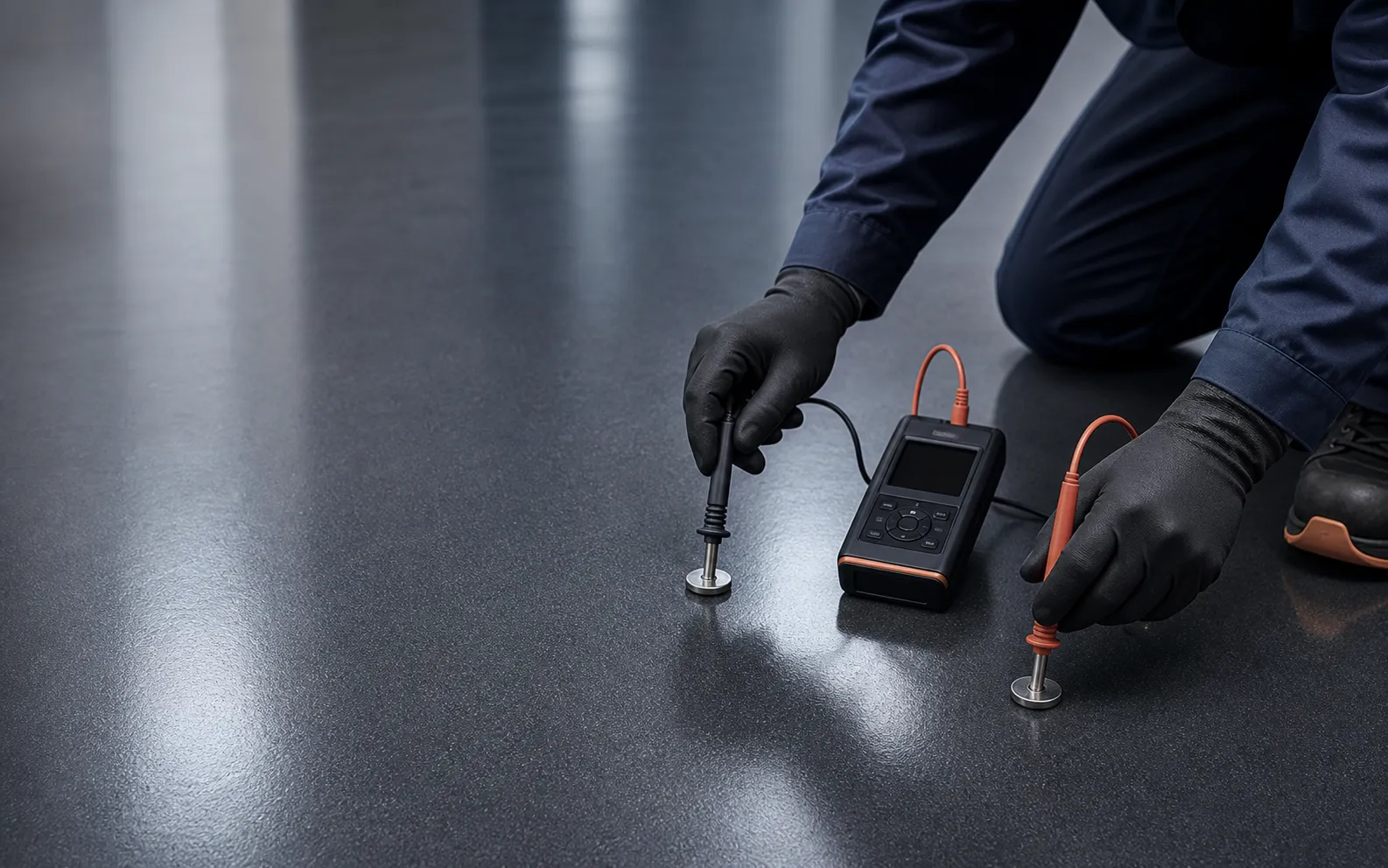
ESD flooring is bought on two words — “conductive” and “dissipative” — that are used interchangeably by people who sell floors and precisely by people who audit them. The difference is a resistance range, the range is set by a standard, and the standard also says how to measure it. This guide sets out the two categories and their numbers, the standards behind them, how a finished floor is verified, and what an epoxy has to do to land in range.
The two categories, by resistance
An ESD floor is defined by its resistance to ground — between a point on the floor surface and the building earth — and by its point-to-point resistance across the surface.
| Category | Resistance to ground | Behaviour |
|---|---|---|
| Conductive | below 1 × 10⁶ Ω | Drains charge quickly; the usual choice for electronics assembly and test, data halls and explosive atmospheres |
| Static-dissipative | 1 × 10⁶ to 1 × 10⁹ Ω | Drains charge in a controlled, slower way; common in control rooms and lower-sensitivity areas |
| Insulative (not an ESD floor) | above 1 × 10⁹ Ω | Ordinary epoxy, vinyl, most tiles — no reliable path to ground |
Both conductive and dissipative floors are ESD floors. Neither is better in the abstract: the facility’s ESD control plan decides which band it needs, and the floor is specified to that band. “Anti-static” is not a third category — it is a loose marketing word for anything that generates less charge, including floors with no path to ground at all.
The floor is one element of a programme
A floor on its own is not ESD compliance. ANSI/ESD S20.20 and IEC 61340-5-1 set the requirement for the flooring and footwear system — a person, in ESD footwear, standing on the floor — at less than 1 × 10⁹ Ω resistance to ground, with a body-voltage alternative for the system as a whole. Footwear, earthing points, wrist straps at seated positions and written procedures are the other elements. An excellent floor with ungrounded connections, ordinary footwear or no verification programme fails an audit quickly.
The standards that set the numbers
Programme standards — ANSI/ESD S20.20, IEC 61340-5-1 — say what the whole system must achieve and how the programme is run.
Test standards — ANSI/ESD S7.1 and IEC 61340-4-1 — define the electrodes, their weight, the test voltage and the procedure for resistance-to-ground and point-to-point measurements on flooring. A specification that names a resistance band without naming the test method is incomplete, because the same floor measures differently at different voltages and electrode loads.
How a conductive epoxy delivers the range
The resistance is a property of the whole build, not the top layer alone.
- Preparation and primer. Sound, dry, mechanically prepared concrete, primed — PrimeBond E20 on a normal slab — so the system stays bonded for its life.
- Grounding layer and earthing points. A conductive primer or a grid of copper tape, connected to earthing points at the spacing the ESD plan requires. This is the path to ground; without it the finish has nowhere to send the charge.
- Conductive wearing coat. StaticGuard CX90, a 100%-solids, solvent-free, self-smoothing conductive epoxy at a minimum of 2.25 kg of binder per m² per coat, targeting 1.0–1.5 mm. Its conductivity is permanent — carried through the body of the film, not by a surface treatment that wears away — and measures 10⁴–10⁶ Ω on average, placing the floor in the conductive band when it is installed and earthed correctly.
- Verification after cure. Resistance to ground at the points the plan specifies, with the test method named, readings recorded and earthing points labelled.
Why thickness is a limit, not a target. Conductivity travels through the fillers in the film, so a thicker film is a longer, higher-resistance path down to the grounding layer. Applied thicker than the data sheet states, the floor measures higher and may fall out of range. It is one of the few floor coatings where more is worse.
Earthing and installation decide real performance
Two floors of the same material measure differently when the earthing differs. The details that decide the reading are the number and spacing of earthing points, the continuity of the conductive layer beneath the wearing coat, the quality of each connection to the building earth, and whether the conductive layer was interrupted at joints, coves and thresholds. These are workmanship items, which is why the floor is measured after installation rather than assumed from the product.
Where each category is specified
| Facility | Usual specification | Why |
|---|---|---|
| Electronics assembly and test | Conductive | Fast discharge; the S20.20 programme is built around it |
| Data centres and server halls | Conductive | Equipment sensitivity; often combined with raised-floor grounding |
| Cleanrooms and pharmaceutical | Conductive or dissipative, by plan | Combined with seamless, cleanable finish requirements |
| EMI/RFI-shielded rooms | Conductive | Part of the shield’s earth continuity |
| Control rooms, board handling | Dissipative | Slower discharge preferred; lower sensitivity |
| Aerospace hangars, munitions, solvent stores | Conductive | Explosive-atmosphere risk, not only component damage |
The ESD flooring page sets these against the Rayson build-ups; the electronics facilities page covers the rest of the floor plate.
Performance is maintained, not just installed
Resistance drifts. Wear thins the film; cleaning products that leave an insulating residue raise the reading; humidity moves it either way. Serious ESD programmes schedule periodic re-testing and prescribe cleaning methods compatible with the floor, so what is maintained is the reading, not just the appearance. A floor that passed on handover and has never been re-tested is an unknown, not a compliant floor.
What a specification and a quotation must state
- The resistance band — conductive or dissipative — and the programme standard it serves (ANSI/ESD S20.20 or IEC 61340-5-1).
- The test method for acceptance (ANSI/ESD S7.1 or IEC 61340-4-1), the test voltage, and the number and location of test points.
- The grounding layout — earthing points, spacing, and who connects them to the building earth.
- The named system with its technical data sheet, and the applied thickness as a stated range with a maximum.
- Verification on the finished floor, with a written record.
A quotation for an “anti-static epoxy” with none of the above is a quotation for an ordinary epoxy in a grey colour. The epoxy contractor guide covers the rest of what an epoxy quotation must show, and epoxy vs PU vs PU-cement covers whether epoxy is the right chemistry for the rest of the floor.
Rayson formulates StaticGuard CX90 in Singapore and publishes its data. Rayson quotes the job, and an applicator in the Rayson network prepares, installs, earths and tests the floor under the workmanship warranty in Rayson’s quotation. Send us the facility’s ESD requirement, the area and the current floor, and we will specify the build-up and quote the work.
StaticGuard CX90 sits within Rayson’s epoxy flooring range, which compares it with the roller-applied and self-levelling builds.